30 Mar ABB Proposal for LRT DC Rectifier System Monitoring
ABB Proposal for LRT DC Rectifier System Monitoring:
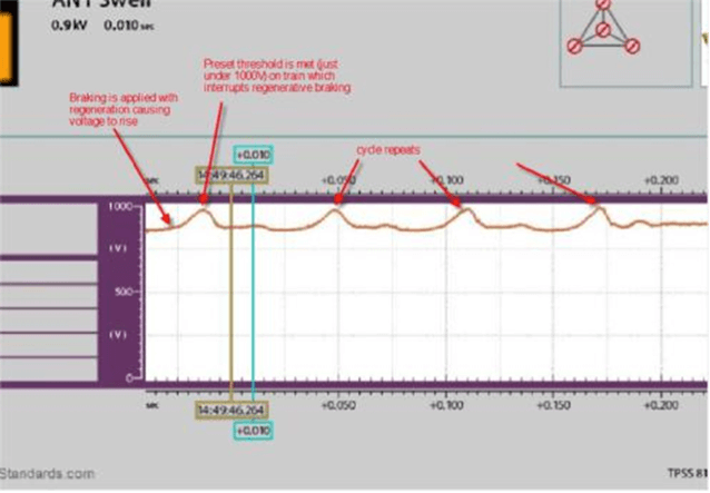
Using PQube 3 to capture millisecond’s snapshots of voltage surge
To investigate into the damage to static inverters on LRVs – to evaluate or determine the source of overvoltage that is experienced by the LRV based on the following LRV reports.
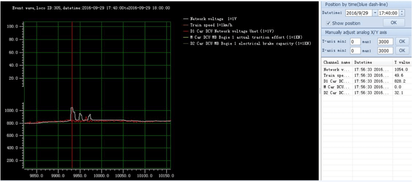
LRV 05 at KKSB Depot, Time 1756:33sec, dated 29 September 2016, peak voltage recorded 1054 VDC.
There have been a number of cases of damage to SIVs on LRVs. One symptom of the events that caused the damage was that there was a high rate of change of voltage (dV/dt) at the current collectors, but the cause of it could not be determined. It was agreed at the meeting to perform a set of tests of the LRVs and the traction supply to try to identify the cause. These tests will be performed first at Ampang Depot, where most of the incidents occurred. Further tests may be required on the Ampang Line Extension and the existing line, depending on the results of the depot tests.
What we needed was data – ideally a snap short of the power over an extended period that would capture any overvoltage or sags the moment they occurred. With its lower price & high level of precision, the PQube seemed the perfect instrument to provide this kind of data. It snapped on the Din rail inside the main panel & could read remotely without the need for software.

Transformer output voltage measurement Point in rectifier panel.

Transducer Terminal block Measurement Point.
As soon as the installation was completed the PQube begin sending snapshots (milliseconds interval) to the monitoring team`s email.

Max voltage 932 voltage, time voltage above TPSS settings 13ms

Max voltage 988 Vdc, time voltage above TPSS settings 10ms
The Test Evaluation
With the snap shots, ABB monitoring team was able to analyse, interpret and understand the basis of the problem, which in turn prompted them to formulate improvisation plan to the existing system.